Connect Arduino to Raspberry Pi
There are few ways to connect MySensors Serial Gateway (Arduino) to Raspberry pi, the easiest one is to connect Serial Gateway (Arduino) via USB port to raspberry pi. This is be easiest way and saves hassle of all wiring on other hand we can use serial pins on raspberry pi to connect to Arduino which is little bit difficult but we are here to build everything our self so let’s build pcb board with all components connected and get this job done neatly right on the Raspberry Pi. If you are using Raspberry pi then you need to enable serial port on GPIO

MySensors Serial Gateway on GPIO Pins
Note: if you have DS18B20 1-Wire digital temperature sensor connected to Raspberry Pi and your Zone Valve relay and boiler relay is connected to raspberry pi GPIO then you don’t need to build a Serial Gateway. you can follow this link to connect DS18B20 to Raspberry Pi.
Hardware Parts List
1 x Arduino Mini Pro 16Hz 5v
3 x 10uf Capacitor
1 x NRF24l01 pa LNA Module
1 x Logic Level Converter – Bi-Directional
Connection/Wires
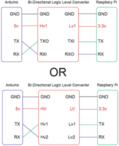
Lets connect Raspberry pi to Arduino through bi-directional logic level converter, remember we are using Aruduino nano pro 5v version and make sure you connect pins correctly otherwise you can damage your rpi

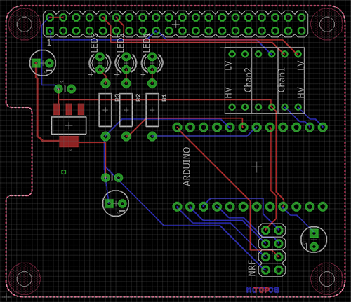
PiHome Serial Gateway Header PCB

MySensors Serial Gateway on GPIO Pins
PiHome Serial Gateway Header Schematic

MySensors Serial gateway Raspberry pi Header Schematic.PNG
MySensors Serial Gateway Sketch
i haven’t modified it that much only important part to look or may need modification on following three settings according to your needs.
#define MY_RF24_PA_LEVEL RF24_PA_MAX
//RF channel for the sensor net, 0-127
#define RF24_CHANNEL 125
//RF24_250KBPS for 250kbs, RF24_1MBPS for 1Mbps, or RF24_2MBPS for 2Mbps
#define RF24_DATARATE RF24_250KBPS
|
1 2 3 4 5 6 7 8 9 10 11 12 13 14 15 16 17 18 19 20 21 22 23 24 25 26 27 28 29 30 31 32 33 34 35 36 37 38 39 40 41 42 43 44 45 46 47 48 49 50 51 52 53 54 55 56 57 58 59 60 61 62 63 64 65 66 67 68 69 70 71 72 73 74 75 76 77 78 79 80 81 82 83 84 85 |
* DESCRIPTION * The ArduinoGateway prints data received from sensors on the serial link. * The gateway accepts input on seral which will be sent out on radio network. * * The GW code is designed for Arduino Nano 328p / 16MHz * * Wire connections (OPTIONAL): * - Inclusion button should be connected between digital pin 3 and GND * - RX/TX/ERR leds need to be connected between +5V (anode) and digital pin 6/5/4 with resistor 270-330R in a series * * LEDs (OPTIONAL): * - To use the feature, uncomment any of the MY_DEFAULT_xx_LED_PINs * - RX (green) - blink fast on radio message recieved. In inclusion mode will blink fast only on presentation recieved * - TX (yellow) - blink fast on radio message transmitted. In inclusion mode will blink slowly * - ERR (red) - fast blink on error during transmission error or recieve crc error * */ // Enable debug prints to serial monitor #define MY_DEBUG // Enable and select radio type attached #define MY_RADIO_NRF24 //#define MY_RADIO_RFM69 // Set LOW transmit power level as default, if you have an amplified NRF-module and // power your radio separately with a good regulator you can turn up PA level. // #define MY_RF24_PA_LEVEL RF24_PA_LOW #define MY_RF24_PA_LEVEL RF24_PA_MAX //#define MY_DEBUG_VERBOSE_RF24 // RF channel for the sensor net, 0-127 #define RF24_CHANNEL 125 //RF24_250KBPS for 250kbs, RF24_1MBPS for 1Mbps, or RF24_2MBPS for 2Mbps #define RF24_DATARATE RF24_250KBPS // Enable serial gateway #define MY_GATEWAY_SERIAL // Define a lower baud rate for Arduino's running on 8 MHz (Arduino Pro Mini 3.3V & SenseBender) #if F_CPU == 8000000L #define MY_BAUD_RATE 38400 #endif // Enable inclusion mode #define MY_INCLUSION_MODE_FEATURE // Enable Inclusion mode button on gateway //#define MY_INCLUSION_BUTTON_FEATURE // Inverses behavior of inclusion button (if using external pullup) //#define MY_INCLUSION_BUTTON_EXTERNAL_PULLUP // Set inclusion mode duration (in seconds) #define MY_INCLUSION_MODE_DURATION 60 // Digital pin used for inclusion mode button //#define MY_INCLUSION_MODE_BUTTON_PIN 3 // Set blinking period #define MY_DEFAULT_LED_BLINK_PERIOD 300 // Inverses the behavior of leds #define MY_WITH_LEDS_BLINKING_INVERSE // Flash leds on rx/tx/err // Uncomment to override default HW configurations #define MY_DEFAULT_ERR_LED_PIN 4 // Error led pin #define MY_DEFAULT_RX_LED_PIN 6 // Receive led pin #define MY_DEFAULT_TX_LED_PIN 5 // the PCB, on board LED #include <MySensors.h> void setup() { // Setup locally attached sensors } void presentation() { // Present locally attached sensors } void loop() { // Send locally attached sensor data here } |
Installing dependencies
Login to your raspberry pi via ssh and issue following commands one by one to install Python, PySerial, MSQL-Python for interfacing with serial port and save data to MySQL/MaridaDB database.
|
1 2 3 4 5 6 7 |
sudo apt-get install python2.7 wget https://bootstrap.pypa.io/get-pip.py sudo python get-pip.py sudo pip install pyserial sudo apt-get install libmysqlclient-dev sudo apt-get install python2.7-dev sudo apt-get install python-mysqldb |

13 comments
do you think rpi gpio can supply enough power to keep things running?
Hi James i had this Serial gateway running for around 8 months and all powered by Raspberry pi GPIO, i have 2amp power supply to power raspberry pi.
Admin
Hi, Is it essential to build Arduino based serial Gateway to “read” wireless sensors? Why nRF can’t be connected directly to Raspberry PI as described here: https://forum.mysensors.org/topic/2437/step-by-step-procedure-to-connect-the-nrf24l01-to-the-gpio-pins-and-use-the-raspberry-as-a-serial-gateway-mysensors-1-x ?
Hi Didzis,
you can use connect nrf to rpi directly but i dont know if pihome python script to read data from nrf network will work, i never got around to try/test it, but i know and i have tested this script with mysensors serial gateway and wifi/ethernet gateway, perhaps you can build this and test this and let us know the outcome? i have added option to have zone and boiler relay and DS18B20 temperature sensors connected directly to raspberry pi and you dont need any gateway for this setup, but if you want to go with wireless options then you need mysensors gateway.
Hi,
Thank’s for reply. I’m going to build your version of serial Gateway. Just PiHome Serial Gateway Header Schematic isn’t readable. Is it somewhere published with better resolution? Probably you can send it to my e-mail?
Hi Didzis,
i have added MySensors Serial gateway Raspberry pi Header Schematic and pcb design to GitHub, check out the pcb folder, you need eagle pcb software to open it. alternately you can save schematic image and zoom it in windows photo viewer sorry site template wouldn’t let me make it bigger.
Thank you
Admin
Thanks! got it.
What kind of data should be here?:
void setup()
{
// Setup locally attached sensors
}
void presentation()
{
// Present locally attached sensors
}
void loop()
{
// Send locally attached sensor data here
}
I’ll have three Battery Powered Arduino DS18B20 Temperature Sensors only.
Hi Didzis,
follow these steps to build battery powered temperature sensors
Hi,
My system is wired except for the sensors, hence I’m using a Serial Gateway, there appears to be a problem at line 89 of check_gw.php, the line is:
$query = “UPDATE gateway SET pid = ‘{$out[0]}’, pid_running_since = ‘{$pid_details}’ LIMIT 1”;
the problem is that $pid_details has not been defined (although it is defined in the wireless code block), I fixed by inserting $pid_details = exec(“ps -p ‘$out[0]’ -o lstart=”); as the preceding line.
regards
terry
@Terry,
thank you for letting me know, i have updated check_gw.php and serialgw.py script, can you test both if you have some free time.
Thank you
Thanks for the update, I’ve installed (with a small change to serialgw.py because I’m running on a Beagebome), will let you know if I have any issues.
I’ve modified boiler.php so that it uses the node child_id, this way I can use multiple sensors on the same sensor interface board, eg:
changed $query = “SELECT * FROM messages_in_view_24h WHERE node_id = {$zone_sensor_id} ORDER BY
to $query = “SELECT * FROM messages_in_view_24h WHERE node_id = {$zone_sensor_id} AND child_id = {$zone_sensor_child_id} ORDER BY
You would also need to change homelist.php eg:
$query = “SELECT * FROM messages_in WHERE node_id = ‘{$sensor_id}’ ORDER BY id desc LIMIT 1 “;
to $query = “SELECT * FROM messages_in WHERE node_id = ‘{$sensor_id}’ AND child_id = {$row[‘sensor_child_id’]} ORDER BY id desc LIMIT 1 “;
a similar change would be needed in chartlist.php
What do you think 🙂
@Terry,
you are right no harm adding sensor child id in condition, i need to think more about chartlist.php somehow i have to make that in loop so sensors id and child get covered automatic without modification in code. thanks for your comments.