Low power relays boards are one of the most common interfaces between a Arduino/Raspberry Pi and the outside world. These relay boards provides electrical isolation between the low voltage circuits of the Arduino/Raspberry Pi and the high voltage loads. So why this I2C relay board?
i2c relay boards only requires 4 pins from Arduino/Raspberry pi to control up to 128 relay.
Raspberry Pi i2c
Example of controlling i2c relay board from Raspberry Pi
1 – +5V
2 – GND (common power supply ground)
3 – SDA (i2C data) Physical Pin 3
4 – SCL (i2C clock) Physical Pin 5
Arduino i2c
Example of controlling the relays from an Arduino:
1 – +5V
2 – GND (common power supply ground)
3 – SDA (I2C data) Physical Pin A4
4 – SCL (I2C clock) Physical Pin A5
Support for i2c relay board for zone and boiler control was long due. The relay board control requires this file easyi2c.py
|
1 2 3 4 5 6 7 8 9 10 11 12 13 14 15 16 17 18 19 20 21 22 23 24 25 26 27 28 29 30 31 32 33 34 35 36 37 38 39 40 41 42 43 44 45 46 47 48 49 50 51 52 53 54 55 56 57 58 59 60 |
#!/usr/bin/env python # Contributed by Raju and updated by Jim # # Use: # import easyi2c # dev = easyi2c.IIC(<device i2c address 7 bit>,<Bus number>) # example # dev = easyi2c.IIC(0x32,1) # dev.i2c([10,1,0,1],1) # sends bytes 10,1,0,1 and returns 1 byte # dev.close() # import io import fcntl I2C_SLAVE=0x0703 # linuxi2c.py # 2017-03-19 # Public Domain # Based on 'notSMB' for an easier way to access the i2c bus using just one # function. The main difference between this and notSMB is that the bus # here will be dedicated to 1 device address class IIC: def __init__(self, device, bus): self.fr = io.open("/dev/i2c-"+str(bus), "rb", buffering=0) self.fw = io.open("/dev/i2c-"+str(bus), "wb", buffering=0) # set device address fcntl.ioctl(self.fr, I2C_SLAVE, device) fcntl.ioctl(self.fw, I2C_SLAVE, device) def write(self, data): if type(data) is list: data = bytes(data) self.fw.write(data) def read(self, count): s = '' l = [] s = self.fr.read(count) if len(s) != 0: for n in s: l.append(ord(n)) return l def close(self): self.fw.close() self.fr.close() def i2c(self,listin,nout): rv=0 self.write(bytearray(listin)) if nout != 0: rv = self.read(nout) return rv |
Here is Example Code:
|
1 2 3 4 5 6 7 8 9 10 11 12 13 14 15 16 17 18 19 20 21 |
#!/usr/bin/env python # Simple test for BV4627 using RPi i2c # use wget http://www.byvac.com/downloads/py/easyi2c.py import easyi2c # have linuxi2c.py in same directory from time import sleep def main(): dev = easyi2c.IIC(0x32,1) # click relays in turn one after the other for n in range(10,18): # always 1 more than needed print "Relay ",n dev.i2c([n,1,0,1],0) # on sleep(0.2) dev.i2c([n,0,0,1],0) # off sleep(0.2) dev.i2c([18],0) # all off just in case dev.close() if __name__ == '__main__': main() |
Basic Steps in Python Script to control relay board.
|
1 2 3 4 |
import easyi2c dev = easyi2c.IIC(0x32,1) # 0x32 is the address of the relay board dev.i2c([n,1,0,1],0) # on dev.i2c([n,0,0,1],0) # off |
Full datasheet is here if you want to see some of the other features (use delay, read back status etc) see datasheet
Raspberry pi Configuration for i2c
Physical pin for i2c on raspberry pi are 3 and 3 whereas in WiringPi i2c pins are 8 and 9. You can verify the address of connected i2c peripherals with a simple one-line but you to enable i2c from Raspberry pi config menu and install i2c tools.
|
1 |
sudo raspi-config |

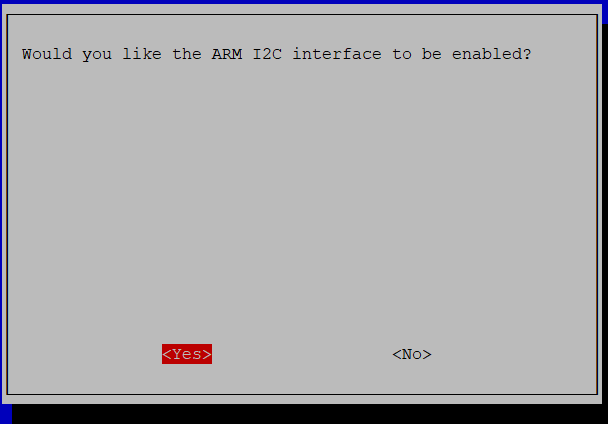
PiHome Enable i2c interface on Raspberry pi Config Menu

PiHome Enable i2c interface on Raspberry pi Config Menu Interface
PiHome Enable i2c Interface Confirmation
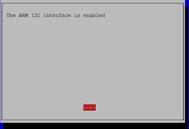
PiHome Enable i2c Interface Confirmation
Once i2c interface is successfully enabled you need to install i2c Tools, to do so run following command
|
1 |
sudo apt install i2c-tools |
After i2c tools are install successfully run following command to check address for connected i2c devices.
sudo i2cdetect -y 1
— gives current i2c address default is 32
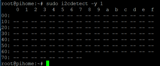
i2c interface address
Python script to change i2c Address:
|
1 2 3 4 5 6 7 |
from notsmb import notSMB bus = notSMB(1) bus.detect() -- this will give current id (50 by default) bus.i2c(50,[82,66],0) --(82 is to set new address, 66 is new value) bus.i2c(50,[85],0) --(resets the board) bus.detect() --(this will give new id (66 gives new address of 33) - exit |
sudo i2cdetect -y 1
— gives new i2c address which is 21 for above settings.
Integrating i2c in PiHome
Python can be executed from PHP script (/var/www/cron/boiler.php) to integrate with exiting system. Controlling i2c relay board requires three variables, one i2c address, relay number and command to for on and off.
i2c Address
i2c address is hard coded in boiler.php file and this can be changed if required in the code on following free locations
- Zone Status
- Boiler On
- Boiler Off
Relay Pin
Boiler and Zone already have GPIO Pin numbers options which is used as pin for i2c relay number and these numbers can be modified from GUI under settings.
Zone Status
|
1 |
exec("python /var/www/cron/i2c/i2c_relay.py 50 ".$boiler_goip_pin." ".$zone_status); |
Boiler On
|
1 |
exec("python /var/www/cron/i2c/i2c_relay.py 50 ".$boiler_goip_pin." 1"); |
Boiler Off
|
1 |
exec("python /var/www/cron/i2c/i2c_relay.py 50 ".$boiler_goip_pin." 0"); |
For previous conversation where i2c started have look at comments on this page
