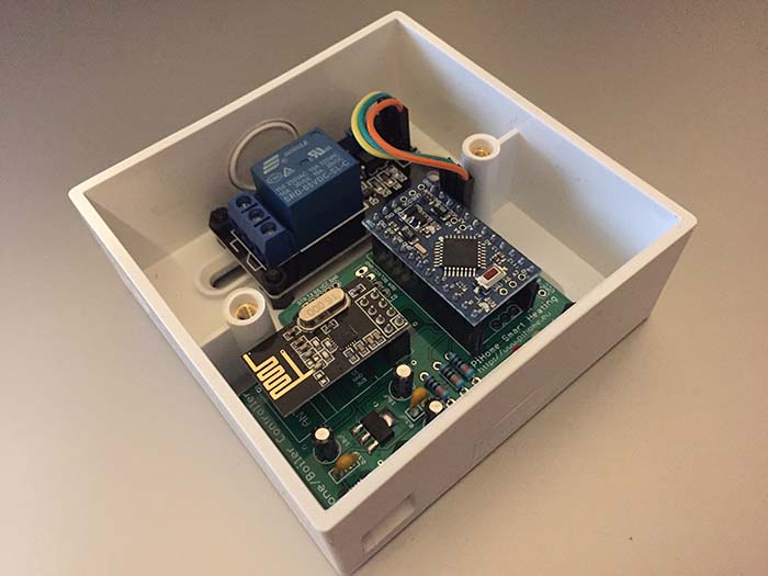
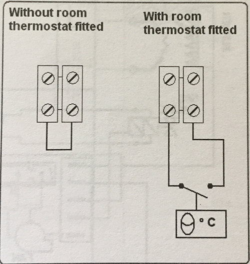
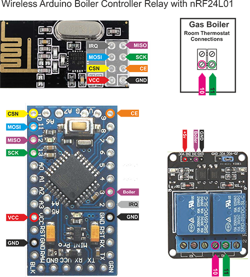
Wireless Arduino Boiler Controller Relay with nRF24L01: Control gas boiler with relay by connecting it to room thermostat connection on gas boiler without passing any current to gas boiler or at least this is how i did it and not to worry about buildup pressure inside heating pipes as gas boiler controller takes care of that itself.
You can control High Voltage electronic devices using relays modules that are readily available in the market. I am using the HL-52S 2 channel relay module, which has 2 relays. The high voltage side output connector has 3 pins, the middle one is the common pin and as we can see from the markings on.
Check out PiHome Shop for all you need for your Smart Heating

Wireless Boiler Controller

Boiler Room Thermostat Connection
One of the two other pins is for normally open connection and the other one for normally closed connection. The reason i m using two channel relay as i can not find any single channel relay with optocoupler ic.

Wireless Arduino Boiler Controller Relay with nRF24L01
PiHome comes with ABSOLUTELY NO WARRANTY, to the extent permitted by applicable law. DO NOT MAKE ANY CHANGES TO YOUR HEATING SYSTEM UNTIL UNLESS YOU KNOW WHAT YOU ARE DOING, contents provided here are for information and education purpose only, I take no responsibility for any loss or damage to you or your property.”
MySensors Arduino Sketch to Control Gas Boiler Relay
Upload wireless Arduino Boiler Controller Relay with nRF24L01 sketch to your Arduino, i would suggest to use Arduino Pro 5v version so you can avoid to have 3v for arduino and 5 volt to power relay module.
|
1 2 3 4 5 6 7 8 9 10 11 12 13 14 15 16 17 18 19 20 21 22 23 24 25 26 27 28 29 30 31 32 33 34 35 36 37 38 39 40 41 42 43 44 45 46 47 48 49 50 51 52 53 54 55 56 57 58 59 60 61 62 63 64 65 66 67 68 69 70 71 72 73 74 75 76 77 78 79 80 81 82 83 84 85 86 87 88 89 90 91 92 93 94 95 96 97 98 99 100 101 102 103 104 105 106 |
// _____ _ _ _ // | __ \ (_) | | | | // | |__) | _ | |__| | ___ _ __ ___ ___ // | ___/ | | | __ | / _ \ | |_ \_ \ / _ \ // | | | | | | | | | (_) | | | | | | | | __/ // |_| |_| |_| |_| \___/ |_| |_| |_| \___| // // S M A R T H E A T I N G C O N T R O L // ***************************************************************** // * Boiler Controller Relay Sketch * // * Version 1.30 Build Date 09/01/2019 * // * Last Modification Date 04/02/2019 * // * Have Fun - PiHome.eu * // ***************************************************************** // Enable debug prints to serial monitor #define MY_DEBUG // Enable and select radio type attached #define MY_RADIO_NRF24 //#define MY_RADIO_RFM69 // Set LOW transmit power level as default, if you have an amplified NRF-module and // power your radio separately with a good regulator you can turn up PA level. //#define MY_RF24_PA_LEVEL RF24_PA_LOW #define MY_RF24_PA_LEVEL RF24_PA_MAX //#define MY_DEBUG_VERBOSE_RF24 // RF channel for the sensor net, 0-127 #define RF24_CHANNEL 125 //RF24_250KBPS for 250kbs, RF24_1MBPS for 1Mbps, or RF24_2MBPS for 2Mbps #define RF24_DATARATE RF24_250KBPS // Enable repeater functionality for this node #define MY_REPEATER_FEATURE //PiHome Node ID #define MY_NODE_ID 100 #include <MySensors.h> #define RELAY_1 3 // Arduino Digital I/O pin number for first relay (second on pin+1 etc) #define NUMBER_OF_RELAYS 3 // Total number of attached relays #define RELAY_ON 1 // GPIO value to write to turn on attached relay #define RELAY_OFF 0 // GPIO value to write to turn off attached relay void before() { for (int sensor=1, pin=RELAY_1; sensor<=NUMBER_OF_RELAYS; sensor++, pin++) { // Then set relay pins in output mode pinMode(pin, OUTPUT); // Set relay to last known state (using eeprom storage) //digitalWrite(pin, loadState(sensor)?RELAY_ON:RELAY_OFF); } } void setup() { } void presentation() { // Send the sketch version information to the gateway and Controller sendSketchInfo("Boiler Relay", "1.2"); for (int sensor=1, pin=RELAY_1; sensor<=NUMBER_OF_RELAYS; sensor++, pin++) { // Register all sensors to gw (they will be created as child devices) present(sensor, S_BINARY); } } void loop() { } void receive(const MyMessage &message) { // We only expect one type of message from controller. But we better check anyway. if (message.type==V_STATUS) { // Change relay state //digitalWrite(message.sensor-1+RELAY_1, message.getBool()?RELAY_ON:RELAY_OFF); if (message.getBool()==RELAY_ON){ Serial.print("Wait Start \n"); wait(20000); Serial.print("Wait End \n"); Serial.print("Relay On \n"); digitalWrite(RELAY_1, RELAY_ON); }else { digitalWrite(RELAY_1, RELAY_OFF); Serial.print("Relay Off \n"); } // Store state in eeprom - we dont need to save relay state as controller take care of this, // saveState(message.sensor, message.getBool()); // Write some debug info #ifdef MY_DEBUG Serial.print("Incoming change for sensor:"); Serial.print(message.sensor); Serial.print(", New status: "); Serial.println(message.getBool()); #endif } } |
If your gas boiler relay module connected directly to raspberry pi gpio pins then follow Raspberry pi Multi Zone Heating Control System Relay. You need to make sure to have WiringPi installed as well on your raspberry pi and have correct WiringPi gpio pins configured for each zone and for gas boiler.


16 comments
any specific reason you are using Channel 125? i have lots of trouble getting my nrf to behave.
// RF channel for the sensor net, 0-127
#define RF24_CHANNEL 125
//RF24_250KBPS for 250kbs, RF24_1MBPS for 1Mbps, or RF24_2MBPS for 2Mbps
#define RF24_DATARATE RF24_250KBPS
No specific reason to use such higher number, as most broadband router used from 0 to 26 so i decided to high number (above 100). These settings i have tried and tested for over a year now.
Do you have any wiring diagram? Or even picture of your relay controller for boiler?
Hi Bill,
i have uploaded all the pictures and wiring diagrams for Wireless Arduino Boiler Controller Relay with nRF24L01
Admin
your site is very helpfull but may be you need to do more screenshots. also can you share connection diagram for this ?
Can i use nrf on raspberry pi and build nrf with arduino relay without mysensors gateway? My 4 zone controller is one location and boiler is in kitchen and i have no way of running cables from zone controller to boiler.
Thank you for help so far i me nearly there
Murt
Hi,
I am using GPIO outputs for both the zone control and boiler relays. Looking at boiler.php, do you thing it might be worth putting in a test to check if gpio_pin is set in the boiler and zone tables, then you either set the pin levels or add to the message queue as required, eg :
if (empty($boiler_goip_pin)) {
if (!empty($zone_gpio_pin)) {
Jus a thought 🙂
@Terry,
thank you for suggestion, i’ll update scripts.
Line #28:
#define MY_NODE_ID 101Should this be ‘100’, as it is in the version on github?
thank you, its changed in post/code.
I have added wait for boiler relay so the boiler isnt turned on straight away. you can set to wait 0ms or increase it as you need.
Hi, i have just been looking at your board schematics and i wanted to build this myself and i was wondering what the value of VARISTOR-7,5 is as i cant seem to find the value listed anywhere
Hi Jacob,
i have purchased this, can not find reference why i used this one, but i have moved on from directly supplying 220v. i m using micro usb connector on pcb and rest is pretty much same
https://www.ebay.com/itm/321024816822?_trksid=p2057872.m2749.l2649&ssPageName=STRK%3AMEBIDX%3AIT