Wireless Arduino Multi Zone Controller Relay with nRF24L01: If your house have Multi Zone Heating then you can control each zone heating independently with raspberry pi and this will save you lot on your heating cost considering that you don’t have to heat all the house all the time. For this purpose you need to build wireless relay switch as Multi Zone Controller so we can open and close zone valve to circulate water in each zone as needed.
Check out PiHome Shop for all you need for your Smart Heating
PiHome comes with ABSOLUTELY NO WARRANTY, to the extent permitted by applicable law. DO NOT MAKE ANY CHANGES TO YOUR HEATING SYSTEM UNTIL UNLESS YOU KNOW WHAT YOU ARE DOING, contents provided here are for information and education purpose only, I take no responsibility for any loss or damage to you or your property.”
Wireless Arduino Multi Zoned Controller Relay with nRF24L01 wiring diagram

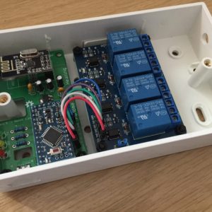
Wireless Arduino Multi Zone Controller Relay with nRF24L01
Make sure you power Relay board with 5v power supply. I suggest to used Arduino Mini Pro/Nano 5v version and have power supply connected to relay board as well. this will save you to have some step-down regulator for arduino.
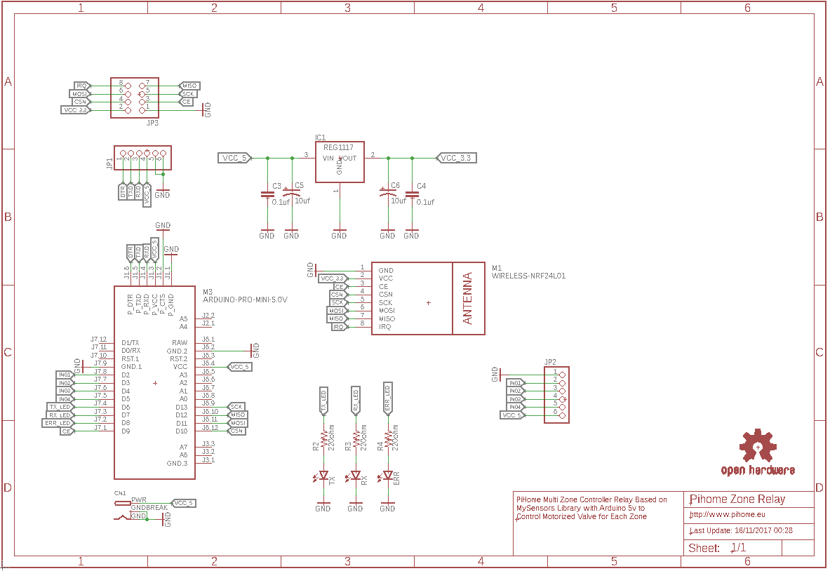
Wireless Arduino Multi Zone Controller Relay with nRF24L01 PBC and Schematic
If you want to have neat and one pcb solution then you can get following pcb made and connect everything as per instructions.

MySensors Multi Zone Controller Relay – Sketch
|
1 2 3 4 5 6 7 8 9 10 11 12 13 14 15 16 17 18 19 20 21 22 23 24 25 26 27 28 29 30 31 32 33 34 35 36 37 38 39 40 41 42 43 44 45 46 47 48 49 50 51 52 53 54 55 56 57 58 59 60 61 62 63 64 65 66 67 68 69 70 71 72 73 74 75 76 77 78 79 80 81 82 83 |
/* PiHome Smart Heating Control ..::Zone Controller Relay::.. */ // Enable debug prints to serial monitor #define MY_DEBUG // Enable and select radio type attached #define MY_RADIO_NRF24 //#define MY_RADIO_RFM69 // Set LOW transmit power level as default, if you have an amplified NRF-module and // power your radio separately with a good regulator you can turn up PA level. //#define MY_RF24_PA_LEVEL RF24_PA_LOW #define MY_RF24_PA_LEVEL RF24_PA_MAX //#define MY_DEBUG_VERBOSE_RF24 //RF channel for the sensor net, 0-127 #define RF24_CHANNEL 125 //RF24_250KBPS for 250kbs, RF24_1MBPS for 1Mbps, or RF24_2MBPS for 2Mbps #define RF24_DATARATE RF24_250KBPS // Enable repeater functionality for this node #define MY_REPEATER_FEATURE //PiHome Node ID #define MY_NODE_ID 101 #include <MySensors.h> #define RELAY_1 3 // Arduino Digital I/O pin number for first relay (second on pin+1 etc) #define NUMBER_OF_RELAYS 4 // Total number of attached relays #define RELAY_ON 0 // GPIO value to write to turn on attached relay #define RELAY_OFF 1 // GPIO value to write to turn off attached relay void before() { for (int sensor=1, pin=RELAY_1; sensor<=NUMBER_OF_RELAYS; sensor++, pin++) { // Then set relay pins in output mode pinMode(pin, OUTPUT); // Set relay to last known state (using eeprom storage) //digitalWrite(pin, loadState(sensor)?RELAY_ON:RELAY_OFF); } } void setup() { } void presentation() { // Send the sketch version information to the gateway and Controller sendSketchInfo("Zone Controller Relay", "1.2"); for (int sensor=1, pin=RELAY_1; sensor<=NUMBER_OF_RELAYS; sensor++, pin++) { // Register all sensors to gw (they will be created as child devices) present(sensor, S_BINARY); } } void loop() { } void receive(const MyMessage &message) { // We only expect one type of message from controller. But we better check anyway. if (message.type==V_STATUS) { // Change relay state digitalWrite(message.sensor-1+RELAY_1, message.getBool()?RELAY_ON:RELAY_OFF); // Store state in eeprom - we dont need to save relay state as controller take care of this, //saveState(message.sensor, message.getBool()); // Write some debug info #ifdef MY_DEBUG Serial.print("Incoming Change for Relay: "); Serial.print(message.sensor); Serial.print(" - New Status: "); Serial.println(message.getBool()); #endif } } |
For Boiler relay controller it is same pin connection apart from you only need one connection to relay, for boiler check this link

8 comments
Do you mind to share connection and some images of multi zone relay? if possible may be more info on how to wire everything.
Hi,
i have plan to prepare some images (may be next week).
Admin
Hi,
How to deal with 2 separate valve manifolds? For I have one at the 1st floor, second one on the 2nd floor 🙂
Regards,
Endre
@Andrew,
if you have two manifold and not located in same location then in that case you need two zone controller and each with different ID number. hope this helps
Hi,
I have a problem with the multi zone controller: every 2-3 days the controller is completely frozen(doesn’t receive any data from the gateway). Normally every few seconds it blinks the TX/RX lights, but when it gets into this state no more activity is on the board. Also the nRF module becomes it’s quite hot.
If I unplug it and then power it up again everything starts working correctly again.
I’ve debugged the gateway and raspberry pi and the database shows correctly that the message has been send to relay module. Also rebooting the gateway and pi doesn’t fix the problem. So i’m sure it’s the multi zone controller.
Many thanks!
Alex
Hi Alex, it could be faulty nRF radio module if you have any spare ones you can try replacing it or you can swap with any other node and see if that fix the problem.